The ESP32-S2 Mini StageKit is a device that shows the custom light shows programmed into Rock Band 3 when using Rock Band 3 Enhanced.
You attempt any of this at your own risk. Incorrectly wiring and powering electronics can result in fires or even worse.
You have been warned!
ESP32-S2 Mini - I used a LONIN S2 Mini.
SK9822 LEDs - I'm using 60 per M, cut and joined at 8 per side to make a square of 32. Although more can be used :)
PSU - The SK9822 LEDs are 0.06amp per segment (each segment has 3 leds @ 0.02amp). So 70 segments is 70 x 0.06 = 4.2amp.
For a 32 LED segment, I've been testing using a standard USB battery pack.
Ensure you use the correct fuse ratings on the LED strips!
Multiple strips can be joined together using the data & clock channels, then feed each strip with it's own power.
Example, I use 4 strips. Each strip has it's own fuse and PSU connection.
- 2 strips x 70 segments = 2 x 4.2amp = 5 amp fuses.
- 2 strips x 40 segments = 2 x 2.4amp = 3 amp fuses.
Ensure you use correct AWG rated wire for your power requirements.
Connect the SK9822...
- GND : Ensure it's to the Ground on the PSU/battery pack, the ESP32-S2 mini should also use the same ground.
- C(lock) : SPI SCLK (GPIO 36) on the ESP32-S2 mini.
- D(ata) : SPI MOSI (GPIO 35) on the ESP32-S2 mini.
- 5V : Positive output on PSU/battery pack.
Download the Arduino IDE. Open the WARNING: DO NOT POWER THE LEDs FROM AN EXTERNAL SOURCE UNTIL THE ESP32 HAS BEEN DISCONNECTED FROM PC. YOU - HAVE - BEEN - WARNED! Now connect the ESP32-S2 mini via USB to a PC. On the ESP32-S2 hold the "0" button down and then press the "RST" button, then let go of the "0" button. This puts the device into program/flash mode. In the Arduino IDE click "Sketch" then "Upload", now wait for the program to compile & upload to the ESP32. You will see a lot of % output until it gets to 100%, then it will complain about not being able to reset the device & give an error. Don't worry, this is normal :) Now disconnect the USB from ESP32 so that it's no longer connected to the PC and then power it by your PSU/Battery pack. Connect a device (phone/pc) to the WiFi hotspot "ESP32_StageKit" using the passcode "1234567890". Using a webbrowser go to "http://192.168.1.1/" and a WiFi setup screen will appear. Enter in your local WiFi details in WiFi SSID & Password. If your network has DHCP then check with your router which IP it will get from the MAC, or enter in manually a static IP & Subnet. Click "Submit" and the device will restart. It will attempt to connect to the WiFi network given, if it fails then the hotspot will re-appear.
When the device connects to your network, open a browser and point to its new IP. Example: I set my DHCP server to assign "192.168.1.99" so I open a webbrowser for "http://192.168.1.99/"
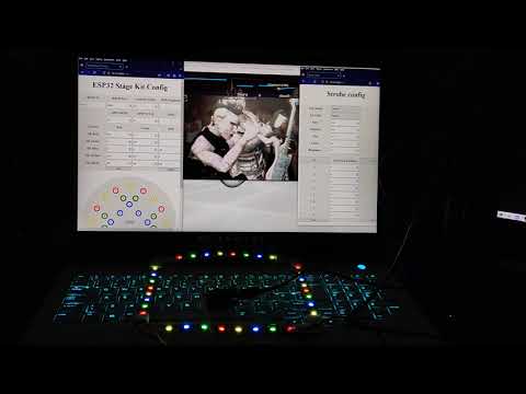
When opened a screen will appear allowing you to configure the leds. The default settings are for ESP32-S2 mini Lonin with 32xSK9822 LED segments.
RB3E IP : Set as the IP of the device where the data will come from, or leave blank to accept from anywhere. RB3E Port : The listening port. Hardware = 21070 Xenia = 20050 or 21070 (if fixed) Ledstrip LEDs : Number of LED segments in the lightstrip. Default = 32 POD Brightness : Default brightness of all LEDs, use -1 to use individual brightness per group. GPIO MOSI : Pin used for Master Out Slave In. Default = 35 GPIO SCLK : Pin used for Clock. Default = 36 DMA : Default = 1 Colours : SK colour can be changed, prefer orange instead of red? Then use 255, 255, 0 SK Strobe : Default is white, but maybe you want blue or green :)
Next is the rough LED layout of a stagekit, clicking each circle will allow you to change the LED numbers to use. Each LED number can then be linked to multiple LEDs, increase with "LED +" & decrease with "LED -". For each number enter in the LED strip position in the middle. At the top you can set the brightness of this group. This only works if "POD Brightness" on main page is set to -1. Click SAVE to save these to the device, else click CANCEL to revert any changes just made. Both will return to first config page.
In the middle of the config screen is a button for "STROBE", click to configure the strobe. You can Enable or Disable the strobe completely, or Enable/Disable using all LEDs. If you want to set only some LEDs as strobe, then you can add & remove LEDs, just like the LED colour groups. There are 4 options for speed : Slow, Medium, Fast, Faster. These are time in milliseconds between flashing.
Remember to click SAVE to save your settings!
RB Enhanced team for pushing out the data over udp.
AchillesPDX for trying to nail the strobe timings.
Sea Dog Andy for the html help, especially the circles :D