- WS-MG90S micro servo
- 2 x ITR8307
- Custom PCB
- Flat cables
- 2 leads wide
- 3 x 3 leads wide
- 4 leads wide
- pin header 1x4
- 3D printed parts
- baseBox
- baseBushing
- encDisc
- encDiscTurningMount
-
Order PCB using gerber, BOM and CPL files:
PcbDesignes/combined/manufacture/gerber.zipPcbDesignes/combined/manufacture/jlcpcbPcbaBOM.csvPcbDesignes/combined/manufacture/jlcpcbPcbaCPL.csv
-
Burn bootloader to PCB. The following instructions are for burning the bootloader using a Raspberry Pi.
(For burning the bootloader with a
stlinkv2on windows, see stlinkv2 on windows. Also see bootloader programmer for pogo-pin connector for PCB programmer)Power PCB via USB from pi and connect:
Prog1:D (swdio) -> GPIO 25 Prog1:C (swclk) -> GPIO 11 Prog1:Reset -> 3.3v (GPIO nr are for a Raspberry Pi 3 B)-
Install OpenOCD on the pi with this guide: https://learn.adafruit.com/programming-microcontrollers-using-openocd-on-raspberry-pi/compiling-openocd
or using apt-get:
sudo apt-get install openocd -
Download bootloader: https://github.com/adafruit/uf2-samdx1/releases/download/v3.13.0/bootloader-itsybitsy_m0-v3.13.0.bin
or latest from: https://github.com/adafruit/uf2-samdx1/releases
-
Put *.bin file in new folder on pi together with the file burnBootloaderWithOpenOCD.txt and rename the script file to
openocd.cfg -
run:
   cd \\|Insert name of folder on pi with the script
   sudo openocd
-
-
Print objects in PrusaSlicer project file
CadFiles/MicroServoMG90S/prusaSlicer.3mfPrint in black PLA:
baseBox.stlbaseBushings.stl
Print in white PLA:
encDisc.stlencDiscTurningMount.stl
Modify the servo according to the Build Video
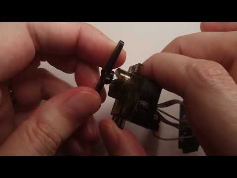
Build steps in video:
-
Disassemble the servo

-
The
encDiscpart has to be completely smooth and free from defects. Getting the required resolution out of a normal FDM 3D printer is basically impossible. So to get a smoothencDiscpart we first need to file it down while spinning it:-
Remove the gear from the motor and mount
encDiscTurningMounton motor axis. Then mountencDisconencDiscTurningMount


-
Apply 3-5 volts to the motor and file down 3D printing seams and printing lines until the surface of
encDiscis completely smooth

-
-
Mount the smooth
encDiscand gear on the motor axis
-
Solder on a 3 lead wide flat cable to each of the two ITR8307 sensors. Make sure that the orientation of the sensors are mirrored


-
Mount the sensors in
baseBoxso that the LED segment (pin 1) of the sensors are oriented towards each other

-
Solder the ITR8307 sensors and potentiometer to the PCB


-
Put
baseBushingon the center axis of the gear box
-
Insert motor into
baseBox, solder motor connections to PCB and screw everything together

-
Done


-
Power servo (5 volt) via pin header and connect to computer via micro USB
-
Run
python3 ./ArduinoSketch/configurationWizard.py -
Create a new configuration file by clicking
Create new, selectdefaultMG90S.has template, and choose communication node nr -
Transfer the initial configuration to the servo by clicking
Transfer to target -
Select
Optical Encoderto calibrate encoderCalibration example:
- Move servo to 100 deg and Lock position by clicking
Lock - Set
Motor pwm valueto 320 - Set
Start motor pwm valueto 450 - Choose position resolution
Fine (~4 min)orUltra (~8 min) - Click
Start calibration
- Move servo to 100 deg and Lock position by clicking
-
Identify system parameters with
Pwm and system identificationCalibration example:
- Move servo to 100 deg and Lock position by clicking
Lock - Set
Motor settle timeto 0.1 s - Set
Min motor pwm valueto 320 - Set
Max motor pwm valueto 1023 - Set
System model cycle timeto 0.6 ms - Click
Start calibration
- Move servo to 100 deg and Lock position by clicking
-
Calibrate motor position dependent disturbances with
Motor cogging torque(optional)Calibration example:
- Click
Set advanced parameters - Set
Control speedto 32 - Set
Inertia marginto 2.0 - Click
OK - Set position resolution to
Standard (~3 min) - Move servo to 100 deg
- Click
Start calibration
- Click
-
Calibrate nonlinearities in output potentiometer with
Output encoder calibration(optional)Calibration example:
- Click
Set advanced parameters - Set
Control speedto 28 - Set
Inertia marginto 1.8 - Click
OK - Set position resolution to
Fine (~4 min) - Move servo to 100 deg
- Click
Start calibration
- Click
-
To test the final configuration select
Test control loop