An Introduction to DALI
#DALI Specifications
- Maximum number of devices: 64
- Number of Groups: 16
- Number of Scenes per Group: 16
- Data Cable: 2 wires
- Data Encoding Method: Manchester
- Data Baud Rate: 1200 baud
- Network Power Supply: 16V DC 250mA
###DALI Transport
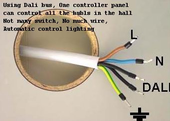
DALI requires 2 wires to devices, in addition to mains cables if required. These wires are not polarity dependant which makes it simple to install. These wires are at ELV (Extra Low Voltage) potential and are looped to all devices. Some devices, such as HF ballasts are mains powered, and only have functional isolation between the mains and the DALI control. This means that even though the DALI control cable operates at ELV potential, it must be treated as if it were at mains potential. A DALI network requires a 24V DC 250 mA power supply to operate. This voltage appears on the data cables and can be used to supply power to peripherals that require it, such as motion detectors. A separate power supply can be used, some manufacturers have DALI gateways with an integral power supply. When choosing a DALI cable, use a mains rated cable with conductor sizes as 1.5mm² avoid runs over 300 Meters
###DALI Devices Power Consumption DALI devices consume power to operate. DALI ballasts have the capability of fully extinguishing the lamps with mains power still applied to the ballast. This can simplify the mains wiring of some implementations as there is no requirement to switch off the mains when the lights are turned off. Careful consideration should be given before deciding to leave the mains permanently applied to the ballasts as the control electronics in each ballast continues to draw energy even when the lamps are extinguished, with some brands of ballast this "off state" power consumption can be significantly high to become an energy management and wiring issue, particularly on sites with large numbers of ballasts.
###DALI Addressing DALI devices have two addresses: Short address - This is a 6 bit number, which allows a maximum of 64 devices on a DALI network. Each DALI device must have a unique address, which is frequently used for normal control of the DALI system. A short address conflict is when two or more DALI devices have the same short address. In this situation device(s) that have the same short address must be re configured to have a unique address. Long Address - this is a 24 bit value that is primarily used for resolving short address conflicts at the time of commissioning. The long address is such a large number that the chances of two in a group of up to of 64 devices having the same long address is small, but it can happen. In this case there is a "Randomise Long Address" command that is used to resolve the long address conflict.
###DALI Grouping A DALI device, such as a HF fluorescent ballast, can be controlled individually via it's short address. In addition to this method of control, DALI devices can be arranged into groups in which all devices of the same Group can interact with each other. For example, a room with 4 ballasts can be changed from off to on in two common ways: Method 1 – Using the Short Address, eg. sending the following DALI messages: DALI Short Address 1 go to 100%
This method has the advantage of not relying on the limited number of scenes available in each ballast, or having programmed each ballast with the required group numbers and scene information. The fade rate of the transition can be chosen on the fly. This method can have an undesirable side effect called "Mexican Wave" when a single large room such as an auditorium contains many ballasts, due to network latency of the comparatively slow 2400 baud rate of DALI. For example, a transition from all on to all off may result in a visible delay between the first and last ballasts switching off. This issue is normally not a problem in rooms with smaller numbers of ballasts.
Method 2 – Using the DALI Group previously defined for the ballasts in the room, eg: DALI Group address 1 go to 100% This method has the advantage of being immune to the “Mexican Wave” effect as described above. This method has the disadvantage of requiring each ballast to be programmed with the required group numbers and scene information, and has a fixed fade rate which is pre set at the time of commissioning.
###Dimming Curve The DALI protocol provides 256 levels of brightness between off and 100%, which is translated to a ballast power level via a logarithmic dimming curve. This curve gives larger increments in brightness at high dim levels and smaller increments at low dim levels. This is an attempt to have a dimming curve which appears linear to the human eye. Sometimes issues arise when different fixtures are used together, such as DALI fluorescent ballasts, DALI ELV Incandescent transformers and phase control dimmed fixtures. When different fixtures are operated together it is often apparent to the eye that the dimming curves do not match, especially at lower levels, due to the lower end distribution of the DALI dimming curve.
##Advantages of DALI
- Simple wiring of control lines (no group formation, no polarity)
- Control of individual units (individual addressing) or groups (group addressing) is possible
- A simultaneous control of all units is possible at any time (built-in initial operation function) through broadcast addressing)"
- No interference of data communication is to be expected due to the simple data structure
- Control device status messages (lamp fault, ....),(report options: all / by group / by unit)
- Automatic search of control devices
- Simple formation of groups through “flashing“ lamps
- Automatic and simultaneous dimming of all units when selecting a scene
- Logarithmic dimming behaviour – matching the eye’s sensitivity
- System with assigned intelligence (every unit contains amongst other things the following data: individual address, group assignment, lighting scene values, fading time, ....)
- Operational tolerances of lamps can be stored as default values (for example for the purpose of energy savings maximum values can be set)
- Fading: adjustment of dimming speed
- Identification of unit type
- Options for emergency lighting can be chosen (selection of specific ballasts, dimming level)
- No need to switch on/off the external relay for the mains voltage (this is done by internal electronic components)
- Lower system cost and more functions compared to 1–10V-systems

###The main features
- easy to install: There are two main power lines, two control lines for installation DALI interface.It is no special requirements on the wire, and no polarity requirement when installing. It only requires the main power line and control line isolation, the control lines without shielding. Just need to pay attention when the control line is current at 220mA, length 300 m, the drop does not exceed 2V.
- easy to operate: DALI terminal interior is smart appliances that can be automatically dimming, switching and fault finding. The control system sends a control command related functions can be achieved, or send status query command cycle, it can be continued to get operational status of each appliance terminal.
- good dimming characteristics: DALI includes 256 brightness and dimming characteristic logarithmic law, dimming curve smoothing that can be achieved by 1% to 100% brightness adjustment.
#DALI Controller
This project is a self contained DALI controller that can be used as a gateway to link multiple DALI networks together. It has an inbuilt DALI network power supply, and a relay to automatically switch off power to ballasts when all are at 0%.

#DALI bus schematics
